Showing posts with label optics. Show all posts

Monday, May 22, 2017

Understanding Relative Illumination

Relative illumination in the context of optical design is the phenomena of image roll-off (e.g. reduction) towards the edge of an eyepiece. This manifests in an image that is brighter at the center of eyepiece relative to the edge of the eyepiece.

Relative illumination is usually shown in a graph such as the one below

This particular graph is from an eyepiece with 60-degree horizontal field of view designed by Sensics. The graph shows how the illumination changes from the center of the lens, e.g. 0, to the edge of the lens, e.g. 30 degrees. The Y axis shows the relative illumination where the center illumination is defined as "1". In this particular eyepiece, the illumination at the edge is just over 70% of the illumination at the center.

This effect can also be viewed in simulations. The first image below shows a simulated image through this eyepiece when ignoring the impact of relative illumination:

Simulated image while ignoring the effect of relative illumination

The second image shows the impact of relative illumination which can be seen at the edges

Simulated image with relative illumination
Relative illumination is perfectly normal and to be expected. It exists in practically every eyepiece and every sensor. It is often the result of vignetting - some light rays coming from the display through the eyepiece to the eye that are blocked by some mechanical feature of the eyepiece. This can be an internal mechanical structure or simply the edge of a particular lens. Light rays from the edge of the display are easier to block and thus typically suffer more vignetting.

When we look at an optical design, we look to see that the relative illumination graph is monotonic, e.g. always decreasing. A non-monotonic curve (e.g. a sudden increase followed by a decrease) would manifest itself as a bright ring in the image, and this is usually not desired.

Thursday, July 21, 2016

Key Parameters for Optical Designs

At Sensics, we completed many optical designs for VR over the years, and are busy these days with new ones to accommodate new displays and new sets of requirements. For those thinking about optics, here is a collection of some important parameters to consider, when focusing in optical systems for VR.

Field of View: typically measured in degrees, the field of view defines what is the horizontal, vertical and diagonal extent that can be viewed at any given point. This is often specified as a monocular (single eye) field of view, but it is also customary to specify the binocular field of view and thus the binocular overlap

Eye relief: typically measured in millimeters, the eye relief indicates the distance between the eye and the closest optical element as seen in the illustration below. 

Eye Relief
Illustration of eye relief

Regular eyeglasses have an eye relief of about 12mm. Advantages of larger eye relief:
  • If the optics are too close to the eye, they generate discomfort such as when the eyelashes touch the optics.
  • If the eye relief is large enough, the system might be able to accommodate people wearing glasses without the need to provide a focusing mechanism to compensate for not having glasses
Disadvantages of larger eye relief:
  • The total depth of the optical system (distance from eye to screen) becomes larger and the overall system potentially more cumbersome.
  • The minimal diameter first optical element is dictated by a combination of the desired field of view and eye relief. Larger eye relief requires the lens to be wider and thus likely heavier.
Eye box: often specified in millimeters, the eye box determines how much the eye can move up/down/left/right from the optimal position without significant degradation in the image quality. Some optical systems such as rifle scopes have very narrow eye box because they want to 'force' the eye to be in the optimal position. Other optical systems, such as HMDs used in soldier training, might desire larger eye boxes to allow the trainee to see a good image even as the HMD moves on the head while the trainee is running. The image quality at the optimal position is most always best, but if the eye box is too narrow, the user will not obtain a good image without tedious adjustments. For instance, the diagram below shows the simulation results of an optical design at the nominal eye position (left) and at 4 mm away from the optimal position:
Eye box simulation
Comparing optical quality at a distance away from the optimal eye position

Material and type of lens: a lens is typically made from optical-grade plastic or from glass. There are hundreds of different optical-grade glass types but only about a dozen optical-grade plastic material. Different material provide different light bending properties (e.g. index of refraction) so it is quite common that multi-element optical systems are made with more than one material. Glass is typically heavier, more expensive to mold, but has greater variety, provides better surface quality and is often physically harder (e.g. more resistant to scratches). Plastic is cheaper and lighter. Additional lens types and non-linear optical elements such as Fresnel Lenses and polarizers are also available.

Distortion: optical distortion is one type of imperfection in an optical design. Distortion causes straight lines not being seen as straight lines when viewed through the optics. An example of this is shown below.

Optical distortion
Optical distortion
Distortion is reported in percentage units. If a pixel is placed at a distance of 100 pixels (or mm or degrees or inches or whichever unit you prefer) and appears as if it at a distance of 110, the distortion at that particular point is (110-100)/100 = 10%. During the process of optical design, distortion graphs are commonly viewed during the iterations of the design. For instance, consider the distortion graph below for a design with 96 degrees field of view (2 x 48): 

Sample Distortion Curve
Distortion graph

The graph shows, for instance, that at 30 degrees away from the center, distortion is still about 2-3%, but at 40 degrees away from the center it increases to about 8 percent. The effect of distortion is sometimes shown in a distortion grid shown below. If the optical design was perfect and had no distortion, each blue cross would line up perfectly at the grid intersection points. 

Distortion Grid
Distortion Grid
Sometimes, distortion is monotonic, meaning that it gradually increases as one moves towards the edge. Non-monotonic distortion can cause the appearance of a 'bubble' if not corrected. 

Chromatic aberration: Just like white light breaks into various colors when passing through a prism, an optical system might behave differently for different wavelengths/colors. This could cause color breakup. It is useful to explore how much the system is 'color corrected' so as to minimize this color breakup. The image below shows a nice picture at the center of the optical system but fairly significant color breakup at the edges. 

Color breakup
Color breakup
Relative illumination: the ability of an optical system to collect light can change throughout the image. Consider a uniformly-lit surface that is viewed through an optical system. Often, the perceived brightness at the center of the optics is the highest and it drops is one moves towards the edges. This is numerically expressed as relative illumination such as the graph below. While the human eye has amazing dynamic range, non-monotonic illumination can cause the appearance of dark or bright 'rings' in the image. 


Relative Illumination

Spot size: imagine a screen with a pattern of tiny dots. In a perfect world, all dots would appear with the same size and no smear when looking through the optical system. In reality, the dot size typically increases as one moves away from the center. The numerical measurement of this is the spot size and diagrams indicating the spot size at different points through the optics often look something like this:

Spot size
Spot Size
Other characteristics: depending on the desired use case, there are often size, weight and cost limitations that need to be considered to narrow the range of acceptable solutions to the specifications. Just like it is easier to fit a higher-degree polynomial to a set of data points because more terms provide additional degrees of freedom, it is easier to achieve the a set of desired optical parameters with additional lenses (or more precisely with additional surfaces), but extra lenses often add cost, size and weight. 

Putting it all together: it is practically impossible to find a car that is inexpensive, has amazing fuel efficiency, offers fantastic acceleration, seats 7 people and is very pleasing to the eye. Similarly, it is difficult to design an optical system that has no distortion, provides wide field of view, large eye box, costs next to nothing and is very thin. When contracting the design of an optical system, it is useful to define all desired characteristics but specify which parameters are key and which parameters are less important.

Sunday, August 9, 2015

The promise and perils of using Fresnel lenses

1: Cross section of  Fresnel lens
2. Cross section of equivlent conventional lens
Image source: Wikipeadia
The use of Fresnel lenses in optical systems VR goggles is not new, but has attracted additional attention in the past year. What are Fresnel lenses and what’s good and not-so-good about using them?

Fresnel lenses were invented nearly 200 years ago by Augistin-Jean Fresnel, a French physicist. The idea is ingeniously simple: the degree to which a lens bends a light ray that hits it depends on material (and hence the index of refraction) from which the lens is made and on the angle of incidence between the light and the surface of the lens. The problem that a Fresnel lens solves is as follows: a classic spherical lens can get very heavy (and expensive) if the curvature and radius is sufficiently large. Since the light bending is essentially determined by the angle at the surface of the lens, could we make a lens that has the same surface curvature at each point of incidence but is not as thick and heavy?

A Fresnel lens (lens 1 in the figure to the right) achieves this by segmenting the classical lens (lens 2) and bringing together small segments of the right curvature. Notice how pretty much each point of the Fresnel lens has the same curvature as the corresponding point in the classical lens.

The original use for which Mr. Fresnel invented the lens was lighthouses (the tall maritime tower, not the Valve tracking system). Focusing the light from the lighthouse into a beam required a very large lens, and using a Fresnel design, this lens could be much thinner, lighter and cheaper than a big chunk of glass. These lenses then also found use a rear window lenses for Minivans (for example, this one) or large lightweight magnifiers.

Weight, thickness and cost are also important in HMDs, and thus many vendors have experimented with such design. Sensics, for instance, has rights to a patent that uses Fresnel lenses in wide-field designs such as the piSight shown below.
This model of the Sensics piSight uses Fresnel lenses as part of the optical system
There are two problems with Fresnel lenses. The main problem is what happens when light hits the ridges, those peaks in the lens that do not correspond to actual curvature in the original lens. When light hits these points it is scatted, and scattered light in an optical system reduces contrast. Thus, you will often see that a Fresnel lens produces a more “milky” image with lower contrast. The second problem is a more technical one – it is more difficult to simulate a Fresnel lens in an optical design software.


Having said that, these systems can be designed and simulated. Here are three variations of 90+ degree optical systems that were designed by Sensics:

90+ degree design using two aspheres
90+ degree design, 1 Fresnel, 1 asphere
90+ degree design, two Fresnel lenses


The first design (two classical lenses) weighs about 16 g per eye. The third design weighs about 2 g per eye. 

As readers of this blog already heard many times, optical design is a study in tradeoffs. If weight is key, Fresnel may be a great option. If performance is most important, Fresnel lenses might not be the first choice.


For additional VR tutorials on this blog, click here
Expert interviews and tutorials can also be found on the Sensics Insight page here

Saturday, January 17, 2015

How Things Work: the Dual-Element Optics of the OSVR HDK

When the OSVR HDK was unveiled last week, one aspect that received a lot of positive reviews was the quality of the optics - clear to the edges, no pre-distortion required. Since the Open-Source Virtual Reality project is indeed open-source, and its Hacker Development Kit will have the full production file available to download in a couple of weeks, I can talk openly about how Sensics designed it for those that are interested.

What's all the fuss about? Take a look at this comparison photo:
Test pattern photographed using an iPhone 4 camera through a dual-element design (left) and single-element design (right)

I took these photos a few months ago when we received the first batch of HDK optics. I found a test pattern on the Internet and displayed it on a 5.5" display, much like the one inside the HDK. I then used an iPhone 4 camera to take both photos. The left photo shows the test image through the HDK dual-element optics. The right photo shows the same test image through a popular single-element eyepiece. I was trying to get the best image in both cases, Is this a scientifically precise comparison? Probably not, but it's quite telling as is.

As you can see, the test pattern is in nice focus at the center of both the left and right photos. However, as you look towards the edges of the photo, the image remains in focus on the dual-element photo but is blurry in the single-element photo. Compare the "gmail" header on the left, quite readable, with the "gmail" header on the right, quite blurry.

You can also see that colors also break up on the right image. You start seeing the separation between red, green and blue. The colors stay intact on the left image. Last, if you look at the three bands of test pattern (right half of left image), you can see that they remain pretty much straight, whereas the same bands on the right image appear curvy.

In short, we are seeing a blurry image, chromatic aberration and geometrical distortion in the single-element design and not so much on the dual-element one.

Is the dual-element design in the HDK perfect? The best Sensics has ever done? The design to beat all designs from here on? Of course not! It's just a good design and solid engineering. Let's look at what makes it better in some aspects than the single-element design.

When we start an optical design project, we look at the requirements. How much field of view are we looking for? What is the screen size we are trying to image? What are the materials we are allowed to use (e.g. plastic? glass?) How much is it allowed to weigh? What are our cost constraints? How much eye relief (distance from cornea to first optical element) do we want? What is the desired eye box (how much the eye can move from the optimal location without significantly losing image quality)? Are we allowing aspheric optics? How wide or deep do we allow the optics to be? and so on...

All of these are constraints and every design has them. But the constraints are different from design to design, much like some cars are built for gas mileage and others are built for super-quick acceleration. That's why there is no single design that is good for every optical problem.

Usually, optics for HMDs have lots of constraints. You typically don't want to make them from glass because glass is heavier than plastic. You have limits on the lens diameter and size because you want to use them in a binocular setting. You don't want them to cost too much because you are aiming at some price target. When you give these constraints to the designer - after he or she finishes pulling their hair out - the design starts.

An optical lens has two sides. The exact curvature of each side can be different. If you have two lenses, you have four surfaces to work with. If you have 5 lenses, you have 10 surfaces to work with. More surfaces mean more degrees of freedom and more degrees of freedom mean that you can meet more of the constraints. So, having more optical elements usually means you can product a better image. In our case better meant less distortion, more focus, less color aberration.

It's almost like curve fitting: trying to fit a polynomial (e.g. y= a + b*x + c*x^2 + d*x^3 + ...) to set of (x,y) points. The more parameters you are allowed to use, the better your fit will be. If your curve is only "y = a", you'd often be in trouble. If you can use "y= a + b*x", you'll have a better fit and if you can use "y= a + b*x + c*x^2" you'll do even better.

So, we decided that a single-element design did not give us a good-enough answer to our constraints and decided to add a second element and give our designers additional degrees of freedom.

Here is what the design looks like


The screen is on the right side. The eye pupil is on the left side. The two lenses are in between: a 32-mm diameter lens closer to the eye and a 43mm diameter lens close to the screen. Note the interesting left-side surface of the bigger lens. It is made this way to optimize the image quality.

Here is what this looks in 3D:


Both lenses are made from optical-grade plastic. The smaller lens is from a material called Zeonex F52R and the larger one is from Polystyrene . There are hundreds of types of optical-grade glass but just a handful of plastics, but plastics are lighter and sometimes cheaper to use. One more constraint to worry about.

Why doesn't everyone use dual-element design? Because others might be focused on different constraints. For instance, dual elements roughly cost twice as much to make as a single element. Dual elements are heavier than a single element. Dual element eyepieces do a better job of controlling color and geometric distortion, but one could correct for color and geometric distortion with the GPU (though I don't know how one can correct for blurriness with the GPU). So, when we designed the OSVR HDK we were focused on some constraints and that's why we chose two elements.

Why not three or four or even five elements? Same story. We don't want it to cost too much. We don't want the optical path to be longer. We want to keep the weight down. Is someone going to soon write a blog post on their 7-element design? Maybe so. I can't wait to read it!


The post "How Things Work: the Dual-Element Optics of the OSVR HDK" first appeared on the VRguy's blog: www.vrguy.net

For additional VR tutorials on this blog, click here
Expert interviews and tutorials can also be found on the Sensics Insight page here

Monday, October 21, 2013

Can the GPU compensate for all Optical Aberrations?

Photo Credit: <a href="http://www.flickr.com/photos/55514420@N00/5192375946/">davidyuweb</a> via <a href="http://compfight.com">Compfight</a> <a href="http://creativecommons.org/licenses/by-nc-nd/2.0/">cc</a>
Photo Credit: davidyuweb via Compfight cc
As faster, newer Graphics Processing Units (GPUs) become available, graphics cards can perform real-time image transformations that were previously relegated to custom-designed hardware. Can these GPUs overcome all the important optical aberrations, thus allowing HMD vendors to use simple, low-cost optics?

The short answer is: GPUs can overcome some, but not all aberrations. Let's look deeper into this question.

Optical aberrations are the result of imperfect optical systems. Every optical system is imperfect, though of course some imperfections are more noticeable than others. There are several key types of aberrations in HMD optics which take an image from a screen and pass it through viewing optics:
  • Geometrical distortion, which we covered in a previous post would cause a square image to appear curved. The most common variants are pincushion distortion and barrel distortion.
  • Color aberration. Optical systems impact different colors in different ways, as can be seen in a rainbow or when light passes through a prism. This results in color breakup where a white dot in the original screen breaks up into its primary colors when passing through the optical system.
  • Spot size (also referred to as astigmatism), which shows how a tiny dot on the original screen appears through the optical system. Beyond the theoretical limits (diffraction limit), imperfect optical systems cause this tiny dot to appear as a blurred circle or ellipse. In essence, the optical system is unable to perfectly focus each point from the source screen. When the spot size becomes large enough, it blurs the distinction between adjacent pixels and can make viewing the image increasingly difficult.
The diagram below shows an example of the spot size and color separation on various points in the field of view of a certain HMD optical system. This is shown for the three primary colors, with their wavelengths specified in the upper right corner. As you can see, the spot size is much larger for some areas than others, and colors start to appear separated.


Which of these issues can be corrected by a GPU, assuming no practical limits on processing power?

Geometrical distortion can be corrected in most cases. One approach is for the GPU to remap the image generated by the software so that it compensates for known optical distortion. For instance, if the image through the optical system appears as if the corners of a square are pulled inwards, the GPU would morph that part of the image by pushing these corners outwards. Another approach is to render the image up-front with the understanding of the distortion, such as the algorithm covered in this article about an Intel researcher.

Color aberration may also be addressed, though it is more complex. Theoretically, the GPU can understand not only the generic distortion function for a given optical system, but the color-specific one as well, and remap the color components in the pixels accordingly. This requires understanding not only the optical system but also the primary colors that are being used in a particular display. Not all "greens", for instance, are identical

Where the GPU fails is in correcting astigmatism. If the optical system causes some parts of the image to be defocused, the GPU cannot generate an image that will 're-focus' the system. In simpler optics, this phenomena is particularly noticeable away from the center of the image. 

One might say that some defocus in the edge of an image is not an issue since the central vision of a person is much better then the peripheral vision, but this argument does not take into account the rotation of the eye and the desire to see details away from the center.

Another discussion is the cost-effectiveness of improving optics, or the "how good is good-enough" debate. Better optics often cost more, perhaps weigh more, and not everyone needs this improved performance or is willing to pay for it. Obviously, less distortion is better to more distortion, but at what price?

Higher-performance GPUs might cost more, or might require more power. This might prove to be important in portable systems such as smartphones or goggles with on-board processors (such as the SmartGoggles), so fixing imperfections on the GPU is not as 'free' as it might appear at first glance.

HMD design is a study in tradeoffs. Modern GPUs are able to help overcome some imperfections in low-cost optical systems, but they are not the solution to all the important issues.


For additional VR tutorials on this blog, click here
Expert interviews and tutorials can also be found on the Sensics Insight page here

Tuesday, September 3, 2013

Overcoming Optical Distortion

In a previous post, we discussed what optical distortion is and why it is important. In this post, we will discuss ways to correct or overcome distortion.
jenny downing via Compfight cc
There are four main options:

1. Do nothing and let users live with the distortion. In our experience, geometrical distortion of less than 5-7% is acceptable for mainstream professional applications. One of our competitors in the professional market made a nice living for several years by selling an HMD that had close to 15% distortion. However, some customers felt that it was good enough and that the HMD had other things going for it, such as low contrast and high power consumption. For gaming, it may be that larger distortion is also acceptable.

2. Improve the optical design. Lower distortion can certainly be a design goal. However, the TANSTAAFL principle holds ("There ain't no such thing as a free lunch", as popularized by Robert Heinlein) and to get lower distortion, you'd typically have to agree to relax other requirements such as weight, material selection, eye relief, number of elements, cost, transmissivity or others. Even for a standard eMagin SXGA display, my company has found that different customers seek different sets of requirements, which is why we offer two different OEM modules for this display, one design with lower weight and the other with lower distortion and generally higher performance.

3. Fix it in the GPU. The Graphics Processing Unit (GPU) of a modern graphics card or the GPU embedded inside many ARM chips are capable of performing geometry remapping to accommodate the geometrical distortion in the optics in a process called texture mapping. The upside of this approach is that it does not increase the direct system cost. The downside is that it requires modifying the program generating the content. If the content comes from a source that you have less control of (such as a camera, or a game that you previously purchased), you are unable to correct for the distortion.

4. Correct it in the goggle electronics. One could construct high-speed electronics (such as these) that perform real-time distortion correction for a known distortion function. This adds cost and complexity to the system but can work with any content regardless of where it came from. Done correctly, it need not add significant latency to the video signal.

Additional options, often application-dependent, also exist. For instance, we have several customers that use the goggles to present visual stimuli to their subjects. If the stimuli are simple such as a moving dot on the screen, the program generating them can take into account the distortion function while generating the stimuli, thus correcting for the distortion without help from the GPU


For additional VR tutorials on this blog, click here
Expert interviews and tutorials can also be found on the Sensics Insight page here.

Saturday, July 27, 2013

What is Geometric Distortion (and Why Should you Care)?

What is Geometric Distortion?

Geometric distortion is a common and important type of optical distortion that occurs in VR goggles as well as in other optical systems. In this post we will discuss the types of geometric distortion and ways to measure the distortion. There are additional types of optical distortions, such as chromatic aberration, and we will discuss some of them in future posts.

Geometric distortion results in straight lines not being seen as straight lines when viewed through the goggle optics.

What are common types of geometric distortion?

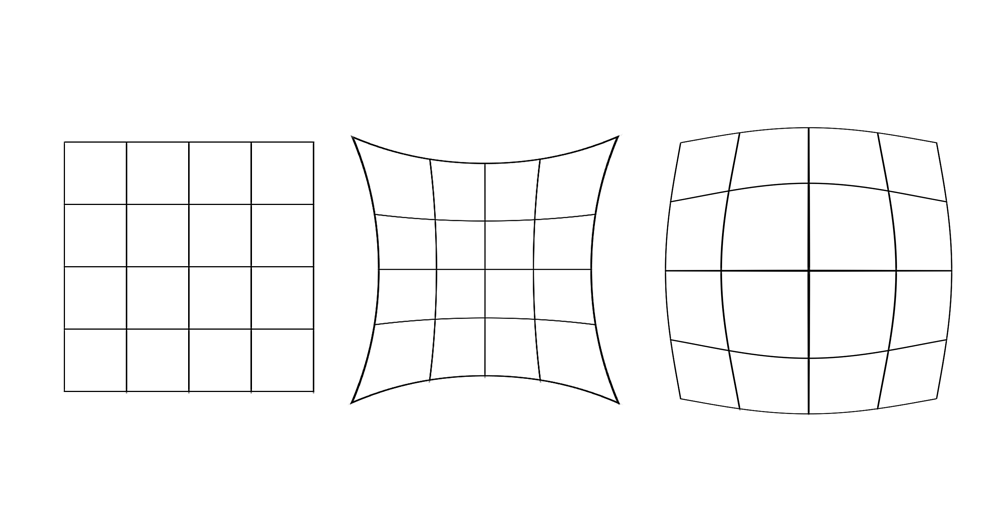
The two common types of distortion are barrel distortion and pincushion distortion. These are shown in the figure below. The left grid is the original image and next to it are pincusion distortion and barrel distortion.
Sourcr: Wikipedia

A barrel distortion is one where the perceived location of a point in space (e.g. the intersection of two of the grid lines) is farther away from the center relative to where it really is. A pincushion distortion is one where the perceived location of a point in space is closer from the center relative to where it really is. Both these distortions are often radial, meaning that the amount of distortion is a function of how far a point is relative to the optical axis (e.g. the center of the lens system). The reasons distortions are radial is that many optical systems have radial symmetry.

Geometric distortion and VR Goggles

Geometric distortion is inherent to lens design. Every lens or eyepiece have some geometric distortion, though it is sometimes not large enough to be noticeable. When designing an eyepiece for a VR goggle, some maximum allowable geometric distortion is often a design goal. Because VR eyepieces need to balance many other desires - minimal weight, image clarity, large eye relief (to allow using goggles while wearing glasses), large eye box (to accommodate left/right/up/down movements relative to the optimal eye position) - the distortion is just one of many parameters that need to be simultaneously optimized.
Photo of a test grid through goggle optics. Picture taken using iPhone camera
Why should you care? Geometric distortion is important for several reasons:
  • If left uncorrected, it changes the perceptions of objects in the virtual image. Straight lines appeared curved. Lengths and areas are distorted. 
  • In a binocular (two-eyed) system, there is an area of visual overlap between the two eyes, which is called binocular overlap. If an object is displayed in both eyes in this area, and if the distortion in one eye is different than the other (for instance, because the object's distance from center is different), a blurry image will often appear
  • Objects of constant size may appear to change size as they move through the visual field.

How is distortion measured?

Distortion is reported in percentage units. If a pixel is placed at a distance of 100 pixels (or mm or degrees or inches or whichever unit you prefer) and appears as if it at a distance of 110, the distortion at that particular point is (110-100)/100 = 10%.

During the process of optical design, distortion graphs are commonly viewed during the iterations of the design. For instance, consider the distortion graph below:

Distortion graph. Source: SPIE
In a perfect lens, the "x" marks should reside right on the intersection of the grid lines. In this particular lens, that is quite far from being the case.

Distortion can also be measured by showing a known target on the screen, capturing how this target appears through the optics and then using specialized software programs to determine the distortion graph. One instance where this is done is during the calibration of a multi-projector wall.

Many distortion functions can be represented as odd-degree polynomials, where 5th or 7th degree is typically sufficiently precise. In formulaic terms:
Typical geometric distortion function

where "r" is the original distance from the center of the image, "a","b","c","d" and "e" are constants and "R" is the apparent distance after the distortion introduced by the optical system. "a" is usually 0.

With any of the above techniques, the constant coefficients can be determined using curve-fitting calculations.

The above also serves a the key to fixing distortion. If it is desired to have a pixel appear to the user in a known distance "R" from the center of the screen, one could solve for "r" above and determine where to put that pixel. For instance, if a system has constant 10% radial distortion as in the example above, placing a pixel at distance 100 would appear as if it is at distance 110. However, placing a pixel at a distance of approximately 91 pixels from center would appear as if it is at distance 100.

The fact that most distortion functions are radial and polynomial also allows for empirical determination. For instance, Sensics has a software program which allows the user to change the coefficients of the polynomials while looking at simulated grid through an optical system. When the coefficients change, the grid changes and this can be done interactively until an approximate correction function for the distortion is discovered

What's next?

In the next post, we will cover several ways to fix or overcome geometric distortions.


For additional VR tutorials on this blog, click here
Expert interviews and tutorials can also be found on the Sensics Insight page here