What is Geometric Distortion?
Geometric distortion is a common and important type of optical distortion that occurs in VR goggles as well as in other optical systems. In this post we will discuss the types of geometric distortion and ways to measure the distortion. There are additional types of optical distortions, such as chromatic aberration, and we will discuss some of them in future posts.
Geometric distortion results in straight lines not being seen as straight lines when viewed through the goggle optics.
What are common types of geometric distortion?
The two common types of distortion are
barrel distortion and
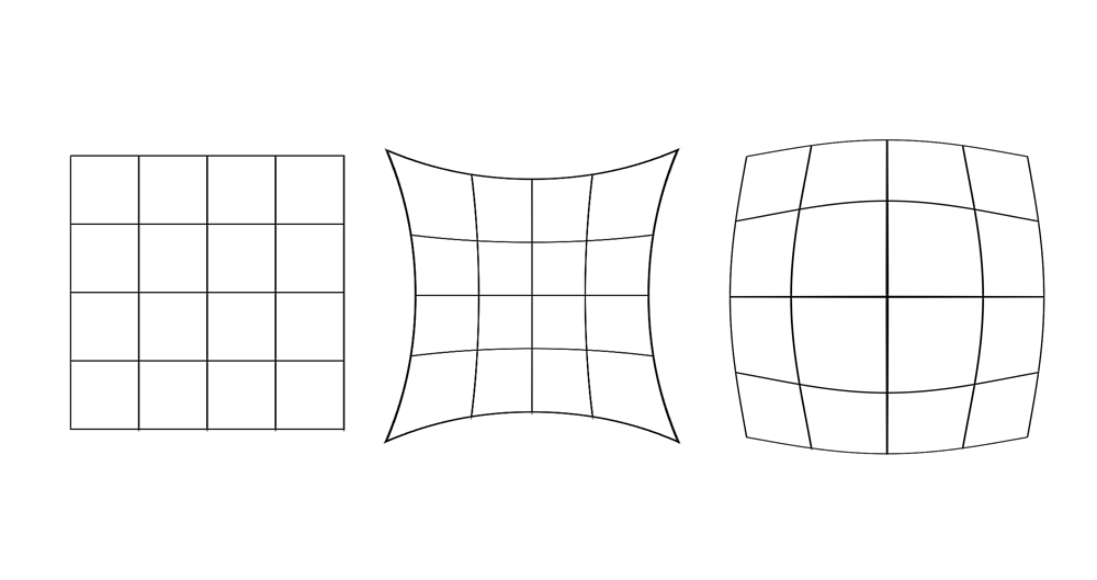
pincushion distortion. These are shown in the figure below. The left grid is the original image and next to it are pincusion distortion and barrel distortion.
 |
| Sourcr: Wikipedia |
A barrel distortion is one where the perceived location of a point in space (e.g. the intersection of two of the grid lines) is farther away from the center relative to where it really is. A pincushion distortion is one where the perceived location of a point in space is closer from the center relative to where it really is. Both these distortions are often radial, meaning that the amount of distortion is a function of how far a point is relative to the optical axis (e.g. the center of the lens system). The reasons distortions are radial is that many optical systems have radial symmetry.
Geometric distortion and VR Goggles
Geometric distortion is inherent to lens design. Every lens or eyepiece have some geometric distortion, though it is sometimes not large enough to be noticeable. When designing an eyepiece for a VR goggle, some maximum allowable geometric distortion is often a design goal. Because VR eyepieces need to balance many other desires - minimal weight, image clarity, large eye relief (to allow using goggles while wearing glasses), large eye box (to accommodate left/right/up/down movements relative to the optimal eye position) - the distortion is just one of many parameters that need to be simultaneously optimized.
 |
| Photo of a test grid through goggle optics. Picture taken using iPhone camera |
Why should you care? Geometric distortion is important for several reasons:
- If left uncorrected, it changes the perceptions of objects in the virtual image. Straight lines appeared curved. Lengths and areas are distorted.
- In a binocular (two-eyed) system, there is an area of visual overlap between the two eyes, which is called binocular overlap. If an object is displayed in both eyes in this area, and if the distortion in one eye is different than the other (for instance, because the object's distance from center is different), a blurry image will often appear
- Objects of constant size may appear to change size as they move through the visual field.
How is distortion measured?
Distortion is reported in percentage units. If a pixel is placed at a distance of 100 pixels (or mm or degrees or inches or whichever unit you prefer) and appears as if it at a distance of 110, the distortion at that particular point is (110-100)/100 = 10%.
During the process of optical design, distortion graphs are commonly viewed during the iterations of the design. For instance, consider the distortion graph below:
 |
| Distortion graph. Source: SPIE |
In a perfect lens, the "x" marks should reside right on the intersection of the grid lines. In this particular lens, that is quite far from being the case.
Distortion can also be measured by showing a known target on the screen, capturing how this target appears through the optics and then using specialized software programs to determine the distortion graph. One instance where this is done is during the calibration of a multi-projector wall.
Many distortion functions can be represented as odd-degree polynomials, where 5th or 7th degree is typically sufficiently precise. In formulaic terms:
 |
| Typical geometric distortion function |
where "r" is the original distance from the center of the image, "a","b","c","d" and "e" are constants and "R" is the apparent distance after the distortion introduced by the optical system. "a" is usually 0.
With any of the above techniques, the constant coefficients can be determined using curve-fitting calculations.
The above also serves a the key to fixing distortion. If it is desired to have a pixel appear to the user in a known distance "R" from the center of the screen, one could solve for "r" above and determine where to put that pixel. For instance, if a system has constant 10% radial distortion as in the example above, placing a pixel at distance 100 would appear as if it is at distance 110. However, placing a pixel at a distance of approximately 91 pixels from center would appear as if it is at distance 100.
The fact that most distortion functions are radial and polynomial also allows for empirical determination. For instance,
Sensics has a software program which allows the user to change the coefficients of the polynomials while looking at simulated grid through an optical system. When the coefficients change, the grid changes and this can be done interactively until an approximate correction function for the distortion is discovered
What's next?
In the next post, we will cover several ways to fix or overcome geometric distortions.
For additional VR tutorials on this blog,
click here
Expert interviews and tutorials can also be found on the
Sensics Insight page here


